Pivot with hub

Center-point steering, in which the kingpin axis is centered on the tire's
contact patch, is part of the DS's front suspension geometry. This design
feature minimises steering inputs as a result of torque being applied to
the wheel, this torque being from power application, braking, or
irregularities in rolling resistance such as those caused by changing road
surface of tire failure.


Pivoting_Wheel.jpg (25652 bytes)
Pivot_Drawing.jpg (72720 bytes)
Fig. 1 : Center-point steering Fig. 2 : Drawing of the pivot with driveshaft and rim
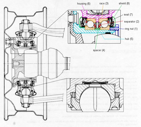
The outboard driveshaft universal joint also has a "bearing" on the wheel hub design :
A tough engineering problem for the early front-wheel-drive engineers was the design of driveshaft universal joints. Citroën had terrible results with the Tracta outboard joints first used on the Traction Avant, and soon substituted a double Hookes joint similar to that on our cars. A problem with the double Hookes joint is that due to its length, stresses on the joint rise dramatically when operated at high angles as the joint is moved inward from the kingpin. In a car such as a Traction or a Panhard, the joint can be seen to move forward and back as the steering is turned. The joint works best if its center (that is, the guide ball between the two cross-arms) is quite near the kingpin line. I 
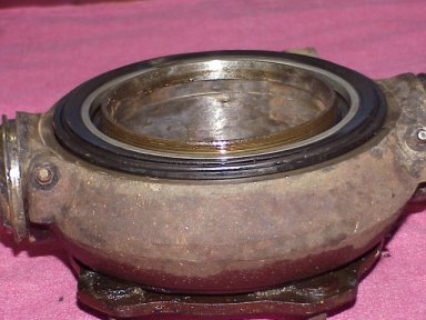
believe this is the problem Citroën solved by placing the outboard joint within the wheel bearing.

The idea of mounting a universal joint within a wheel bearing was not unique to Citroën. Vittorio Jano's Lancia Aurelia, a contemporary of the DS19, used a similar design. But the Lancia used it at the rear; Citroën's front-drive design was far more ambitious.

Modern Rzeppa joints, now almost "universal" on modern front-drive cars, are much more compact and can be mounted inboard of the wheel bearing without problem.

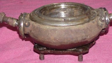
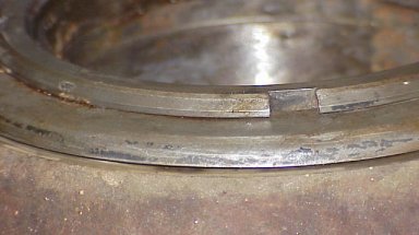
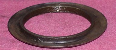
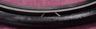
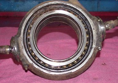
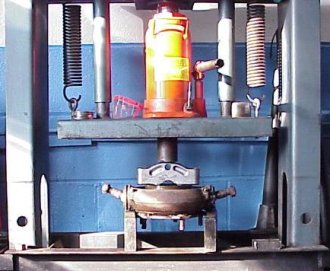
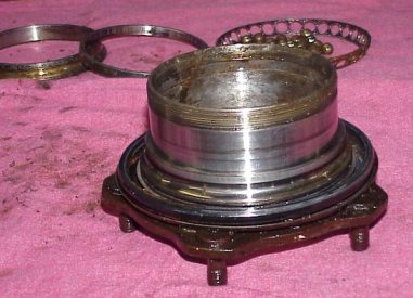
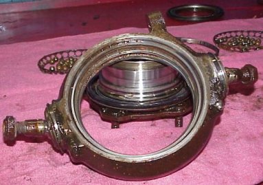
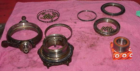
The pictures below show a pivot assembly being disassembled step by step.
pivot1a.jpg (19865 bytes) pivot2a.jpg (17777 bytes)
Fig. 3 : complete pivot with hub Fig. 4 : Detail of ring nut with notch and shield
Fig. 3 shows the (damaged by rust) pivot unit on the bench waiting for disassembly. One can see the notch in the ring nut (1) which accepts the special tool which Citroën does not sell. Rotating with the hub (5) and ring nut (1) is the pressed steel shield (8).
Fig. 4 shows the small clearance between the shield and the housing, which is part of a labrynth seal (7) for the bearing.

A note on greasing the hub bearing :
Since there is no grease nipple for the hub bearing and since the shield is not easily removable it is not possible to apply new grease to the bearing in an easy way. Obviously Citroën designed this bearing to last for the life of the car !

On the DS/ID models with the single-bolt-wheels a similar shield is more easy to remove. On those cars one could try to grease the bearing by injecting grease through the seal with a sharp hollow needle. However this is not recommended !

When Citroën designed the bearing to last for the life of the car they were most probably not thinking about 25 or even 40 years ! Click here for a suggestion on how and where to mount a grease nipple can be found here.

pivot3a.jpg (26473 bytes)
pivot4a.jpg (15809 bytes)
pivot5a.jpg (11519 bytes)
Fig. 5 : Ring nut removed Fig. 6,7 : Underside of the ring nut, detail of grease seal
Fig. 5 shows the assembly after removal of the ring nut. The nut was extremely tight; it was damaged beyond further use by using a pneumatic hammer to turn it. If one wished to repair an unit a proper tool would need to be made.

With the nut and steel shield removed the seal becomes visible. This seal is quite complicated and interesting. The outside of the seal is a light press in the housing. There is a small lip on the seal which lightly contacts the underside of the shield creating the other part of the labrynth. Click here for more detailed pictures of the seal.

Fig. 6  shows the underside of the ring nut with pressed-on shield. The actual grease seal is axial rather than radial. There is a lip visible at the top in fig. 7 which contacts the face of the inner race (3) of the bearing.
pivot6a.jpg (32056 bytes) pivot7a.jpg (26688 bytes)
Fig. 8 : Grease seal removed Fig.9 : Pressing the hub out of the housing
Fig. 8 shows the unit after removing the seal. The rust damage to bearing can be seen between "10:00 and 12:00" on the housing (6).

Fig. 9 shows how the unit was setup in the press to remove the hub (5) from the bearings. It was a surprisingly light press fit.
pivot8a.jpg (28575 bytes) pivot9a.jpg (30151 bytes)
Fig. 10 : The hub Fig. 11 : The housing
Fig. 10 shows the hub with the outer seal and the inner race of the outer bearing still in place. In the background is, left to right, the inner race of the inner bearing, the selective spacer between the inner races which adjusts preload of the bearings, and the bearing separator with a bunch of balls.

Fig. 11 shows the housing with outer races in place. If one were to install a grease fitting, I believe grease should be injected in the space between the inner and outer bearings. A relief orifice could be drilled diametrically opposite the grease fitting to relieve pressure.
pivot10.jpg
Fig.12 From left to right : a bearing separator, a race, the spacer and the other separator together with some balls.
pivot11.jpg
Fig. 13 All parts together
Fig. 13 is a general view of all the parts. At the lower right is a wheel bearing for a 1991 Audi 100, a car similar in size and mission to the DS. It is included to provide a perspective on the design of our cars.


Pictures and text by Carter Willey