|
|
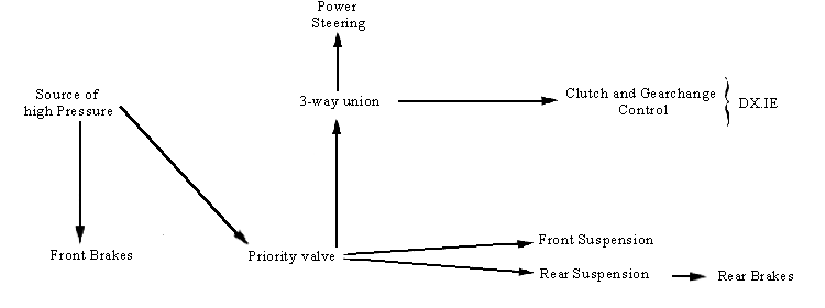
Simplified diagrams of the circuit layouts :
|
DS 21 - DS 19 A (DX - DY) |

|
DS 21 M - DS 19 MA (DJ - DL) |

| DS 21 - DS 19 A (DX - DY) (Since December 1967) DS 21 (DY) Safari 21 - 19 A (DXF - DYF) Optional hydraulic clutch and gearchange control. Safari 20 (DYF) |

| DS 21 M (DJ) - DS 19 MA (DL)
(Since December 1967) DS20 M (DL) Safari 21 - 19 A (DJF - DLF) Safari 20 (DLF) |

| ID 19 B - ID 20 (DV - DT) |

|
DS 21 with Electronic Fuel
Injection from September 1969 |
