Source of pressure

| Circuit Layout | Reservoir | High Pressure Pumps | 7-Cyl. High Pressure Pump | Main Accumulator | Pressure Regulator |


I CIRCUIT LAYOUT

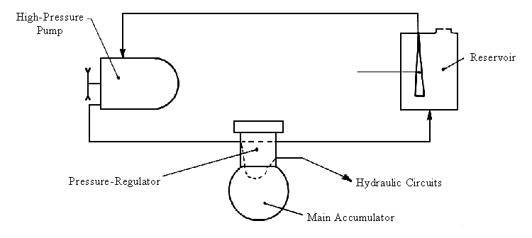
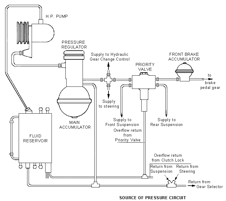
  • The units comprising the source of pressure are as follows :
    • The hydraulic reservoir.
    • The high pressure pump.
    • The high pressure regulator.
    • The main pressure accumulator.


  • To ensure the correct operation of all the hydraulic units a certain minimum pressure must be maintained in their supply circuits.
    To avoid making the pump stop and start for each demand of hydraulic pressure, a certain amount of fluid is stored at a higher pressure than the minimum operating pressure.
  • As long as the pressure remains between the storage pressure and the minimum operating pressure then the pump draws fluid from the reservoir and returns it wichout generating any pressure, this is the rest-period for the pump.
  • The reserve of pressure is maintened by the main accumulator.
  • The maximum and minimum pressures are controlled by the pressure-regulator which causes the flow of fluid to be directed to :
    • either the main accumulator (pumping under pressure)
    • or the reservoir, (pumping without pressure).
II RESERVOIR

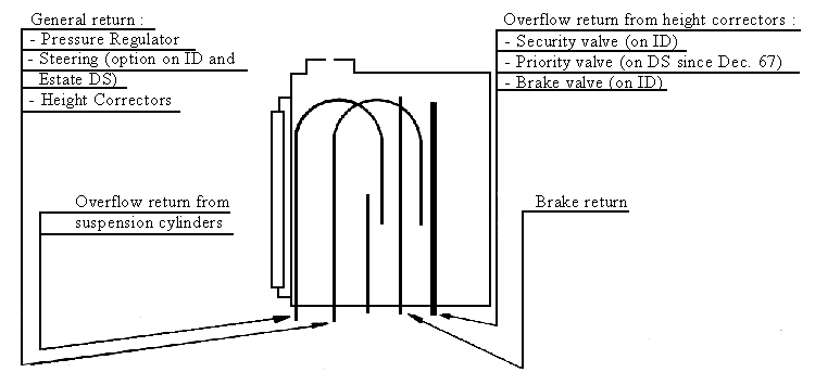
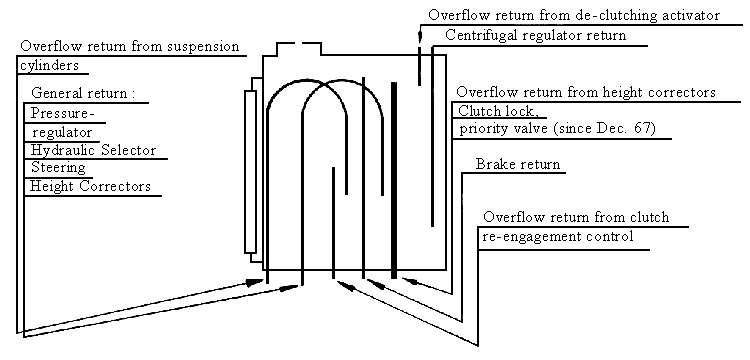
1) A metal Container with external sight tube showing " max " and " min " levels.
  • The reservoir has an internal baffle to allow fluid returning to the tank to settle and deaerate and to prevent surging. It is vented to atmosphere by a small hole in the filler cap.
  • A rubber pipe connected to the base of the Container facilitates its draining.
  • There are two types of reservoir :
    • One for D models equipped wich hydraulic gearchange and clutch (DS 21 - DS 19A - 
      DS 20 - Estate 21 - 19A - 20).
    • The other for D models wich manual gearchange and clutch.
2) Connections

a) Reservoir for vehicles wich hydraulic control of gearchange and clutch.

b) Reservoir for vehicles wich manual control of gearchange and clutch.
 

3) Reading the hydraulic fluid level
  • The hydraulic fluid level is checked wich the engine running and the manual height control lever in the "high" position.

III - HIGH PRESSURE PUMPS

  • There are two types of pumps :
    • A single-cylinder pump : Fitted to ID 19 and ID 20 models in standard trim. It is fitted on the LH side of the cylinder block.
    • A seven-cylinder pump : Fitted to all other D models, also to ID 19 and ID 20 models if fitted with the optinal power steering. It is fitted on the RH side of the gearbox bellhousing, driven at 1/2 engine speed by a pair of belts and pulleys.
  • Only the seven-cylinder pump will be studied in detail. The single piston of the ID pump is driven by an eccentric on the camshaft, and functions in a way similar to that of a single DS piston.

IV-SEVEN-CYLINDER HIGH PRESSURE PUMP

1) General Details :
  • This is a volumetric pump : the swept volume remains the same whatever the pressure.
  • It comprises several pistons arranged in such a way as to provide a continuous flow of fluid and at the same time provide the necessary pressure on the fluid.
    • The odd number of pistons is due to consideration of hydraulic factors. (Smoother fluid flow).
    • The number 7 was chosen for reasons of manufacture (diameter of pistons for example) and size.
2) Description :
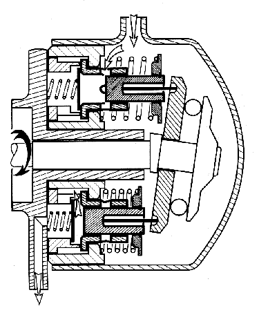
  • The pump comprises 7 identical elements disposed in a circle. A swashplate controls the movement of the pistons by small push-rods.
    • The wall of each cylinder has 4 holes : these are the inlet ports.
    • Each element has a non-return valve held on its seat by a spring. All the outlets are inter-connected and are in turn connected to the supply outlet of the pump.
  • So that the push rods are not drawn round, the swashplate is prevented from turning. It gives only an oscillating movement.
3) Operation :
a) Inlet and filling
  • During its return travel imparted by the return spring, the piston causes a depression in the cylinder. When the inlet ports are opened, fluid in the pump body enters the cylinders.
  • This depression is communicated to the pump body, ensuring the supply of fluid from the reservoir.
b) Compression and delivery
  • Compression starts when the inlet ports are closed.
  • When the pressure in the cylinder is greater than that in the system, the non-return valve opens and delivery takes place.
  • The non-return valve closes by the action of the spring. The pressure existing in the system holds the valve shut on its seating.
c) Piston Travel
  • While the pump shaft completes a half turn, the piston is made to move a distance which is its total stroke.
  • A complete turn of the pumpshaft thus gives a complete cycle. (inlet and Delivery) for each piston.

To see how a 7-piston HP-pump works click one of the links below:
Animated GIF of a HP-pump (83 kb)
Interactive Java animation of a HP-pump (88 kb)

4) Delivery :
  • The manufacturing tolerances of the pump parts are such that it is necessary to position the piston accurately in its sleeve to obtain the correct delivery.
    • This setting determines the piston stroke, and thus its maximum delivery.
    • The setting consists of allowing a clearance of 0.5 mm between the disc valve and the piston crown, achieved by the use of pushrods of different lengths.
  • The pump delivery is 2.80 cc per turn or 840 cc per minute at an engine speed of 600 rpm with a new pump. (The pump runs at half engine speed).
5) Pressure :
a) Minimum Pressure
  • While the pump is idling, the pressure is only enough to return the fluid to the reservoir through the pressure-regulator.
b) Maximum Pressure :
  • Theoretically there is no limit to the maximum pressure.
  • In practice, the maximum pressure is controlled by the pressure-regulator.

V-MAIN ACCUMULATOR

1) General Details :
  • The accumulator improves the flexibility of the system.
    • By immediately supplying fluid in the event of a heavy demand.
    • By allowing the pump to idle and eliminating repeated cutting-in and out.
    • By eliminating shocks in the hydraulic system. (As a damper.)
  • Since April 1969 the D models may be equipped with either of two types of main accumulator.
    • Machined, forged steel accumulator. - Pressed steel accumulator
2) Description :
a) Forged steel accumulator
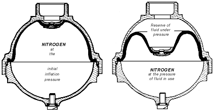
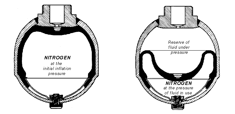
  • This is a sphere divided internally in two portions by a flexible diaphragm, one of These portions is filled with nitrogen under pressure, the other, connected to the pressure regulator, receives the fluld.
  • The sphere comprises two halves screwed together, the force which rends to separate the two halves is taken by a straight-sided thread.
  • The diaphragm : made of synthetic rubber, is held between the two half-spheres which ensure a good seal. A metal cup is fixed in the centre of the diaphragm.
  • The nitrogen : is fed in by way of the hollow filler screw. When no fluid is present it occupies the sphere's whole volume, holding the diaphragm against the sphere and the cup against its seat. The gas pressure is thus the initial inflation pressure of the accumulator.
b) Pressed steel accumulator
  • This is also of spherical shape, comprising a pressed steel globe, to which is welded a machined base.
  • The diaphragm is held between the sphere and a retaining plate. A plastic cup is fixed in the centre of the diaphragm.
  • The nitrogen is introduced into the sphere in the same way as for the previous accumulator, and works in exactly the same way.
3) Particular points
  • When the accumulator contains a reserve of fluid under pressure, the diaphragm is in a certain position and the gas is compressed to a pressure higher than that of its initial inflation. On either side of the diaphragm, gas and fluid are at the same pressure and the diaphragm is in a state of equillbrium.
  • When fluid is used (a drop in volume and pressure of the fluid), the compressed gas expands to compensate for these changes and the flexible diaphragm takes up a different position of equilibrium. The gas and fluid are still at identical pressures, but of a lower value.
  • This condition continues until the initial inflation pressure of the accumulator is reached. Then the diaphragm comes into contact with the shell of the accumulator.

NOTE : The flexible diaphragm plays a passive role in the work of the accumulator, simply that of separating the gas and fluid.

4) Identification of the accumulator
  • The accumulators are marked with a number punched on the head of the filler screw.
    40 for vehicles with the ID type brake system ID 19B (DV) & ID 20 (DT)
    65 for other D models.

VI - PRESSURE REGULATOR

The Pressure Regulator controls

  • A minimum pressure necessary for the proper functioning of the hydraulic units.
  • A maximum pressure to create a reserve of fluid under pressure in the accumulator, and to limit the maximum pressure supplied by the pump.

A - PRESSURE REGULATOR - up to May 1969.

1) Description

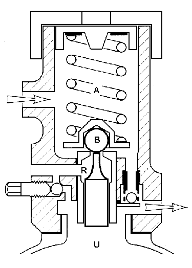
The Pressure Regulator comprises basically three chambers interconnected via two valves.

  • Chamber A connected to the feed from the pump.
  • Chamber U connected to the accumulator and the supply to the units.
  • Chamber R connected to the fluid reservoir.
  • Non-return valve : allows fluid to pass only from A to U.
  • Valve between chambers A and R : controlled by the pressure in chamber U by way of a piston in contact with the ball B of the valve.
  • Pressure-release screw, which permits the fluid in the accumulator and supply circuits to be released back to the reservoir, if required.
2) Operation :
a) Rise of Pressure
  • Pressure rises in the chamber A, lifts the ball of the non-return valve and enters the accumulator U. There is no pressure in chamber R.
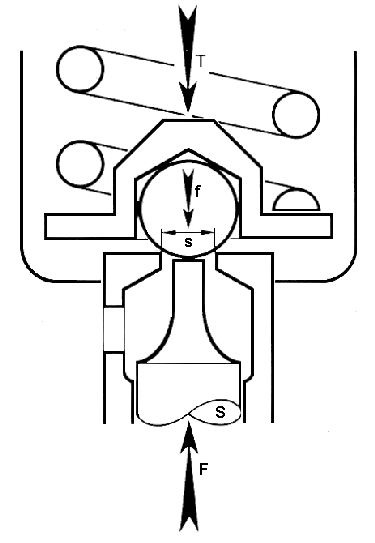
  • Pressure acting on the surface 's' of the ball creates a force f = P x s which tends to force the ball on to its seat.
  • This same pressure acting on the piston head (in chamber U) creates a force F= P x S which tends to lift ball off its seating.
  • The surface S being larger than s, the result of F and f : (F - f) would lift the ball off its seat as soon as pressure arrives. To hold the ball on its seat until a certain pressure (cut-out pressure) a spring A is situated under the ball.
b) Cut-out
  • When the product (F - f) exceeds force T, the ball B is lifted off its seat. Pressure drops in chamber A and the ball of the non-return valve seats again.
  • Since the pressure in chamber A drops to nil, the force F also becomes nil thus increasing the strength of F over T which helps to maintain the cut-out condition.
  • The pump circulates fluid back to the reservoir without pressure.
c) Cut-in :
  • The use of fluid leads to a drop in pressure in the accumulator and the force F weakens. When T becomes the stronger it forces the ball B on to its seat.
  • Pressure rises in chamber A, creating again a force F which helps the spring T.
  • The pump circulates fluid under pressure to the chamber A and U.
3) Identification of Pressure Regulators

Pressure Regulators fitted to cars with the 7-cylinder type pumps and the single cylinder pumps are different. They differ only by their operating pressures :

  • P.R. for single-cylinder pumps : up to mid-February 1969.
  • Marking : No groove on the lower part of the end cap.
    Pressures : cut-out 130 - 140 bars (1850 - 1990 psi)
    cut-in 100 - 110 bars (1420 - 1560 psi)
  • P.R. for 7.cylinder pumps, and for single cylinder types from mid-February 1969
  • Marking : a circular groove on the lower part of the end cap.
    Pressures : cut-out 150 - 175 bars (2130 - 2490 psi)
    cut-in 125 - 140 bars (1775 - 1990 psi)


B - PRESSURE REGULATOR - since May 1969. Pilot-Valve Regulator

1) Description

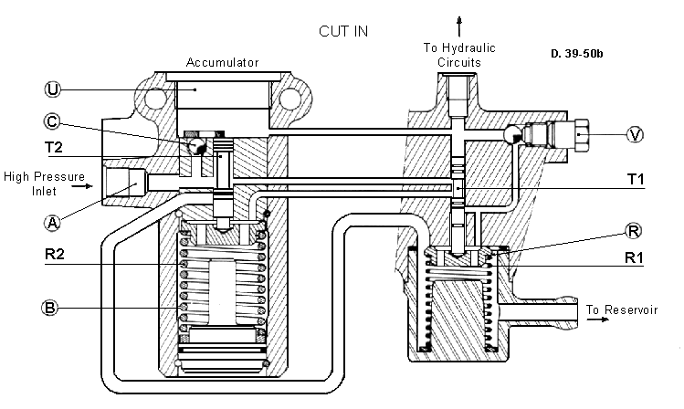
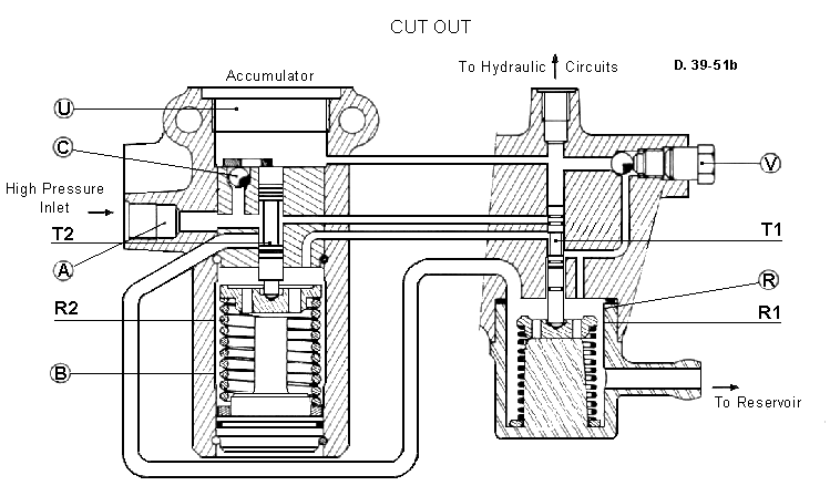
The Pilot-Valve Regulator comprises basically 4 chambers interconnected via a non-return valve and two slide valves.

  • Chamber A : connected to the feed from the pump.
  • Chamber U : connected to chamber A, the accumulator and supply to units.
  • Chamber B : connected to chamber A or chamber R depending on the position of the pilot valve T1.
  • Chamber R : connected to the fluid reservoir.
  • Pilot Valve T1 : allows the fluid to flow into chamber B or from chamber B to chamber R. It is controlled by the pressure of the fluid in chamber U
  • Slide Valve T2 : allows fluid to flow from chamber A to chamber R depending upon its Position. It is controlled by the pressure of the fluid in chambers U and B.
  • Non-return Valve C : allows fluid to pass only from chamber A to chamber U.
  • Pressure-release screw V : allows the fluid in chamber U to escape back to the reservoir via chamber R, if required.
2) Operation
a) Rise of pressure
  • Fluid from the HP pump (in chamber A) rises in pressure in chamber U and the supply circuits by lifting the non-return valve C.
    This pressure rises simultaneously in chamber B via pilot valve T1.
b) Cut-out
  • The rising pressure in chamber U creates an increasing force F on the upper face of the pilot valve T1 which tends to force the slide valve downwards. As soon as this force F becomes stronger than force of spring R1, the pilot valve T1 moves downwards slightly, cutting off the supply of high pressure fluid to chamber B.
  • Meanwhile the pressure continues to rise in chamber U and the pilot valve T1 is forced further down and connects chamber B to the reservoir via chamber R.
  • When the pressure in chamber B drops to nil, the slide valve T2, now subjected to the pressure in chamber U, moves down and compresses the spring R2. This slide valve connects the feed from the HP pump (chamber A) to the chamber R and to the return to the reservoir.
  • The pressure existing in chamber U closes the non-return valve C.
  • The pump circulates fluid back to the reservoir without pressure.
c) Cut In
  • The use of fluid leads to a drop in pressure in the accumulator and chamber U.
  • The pilot valve T1 moves up under the influence of the spring Rl. First it closes the port leading to chamber R, then connects the fluid feed from the pump to chamber B.
  • At this point, the slide valve T2 under the influence of spring R2 moves up and closes the return to the reservoir via chamber R.

The pump circulates fluid under pressure to chamber U.

d) Operating Pressures

Cut Out Pressure : 162 - 175 bars (2305 - 2490 psi)
Cut In Pressure : 140 - 147 bars (1990 - 2090 psi)


Back to top of page