Suspension

| General Details | Description | Operation | Circuit layout | Height correction | Identification of parts |


I - GENERAL DETAILS

Two fluids permit the functioning of the hydropneumatic suspension : a liquid and a gas.

  • The gas constitutes the springing medium.
  • The liquid provides a means of connecting the unsprung items of the vehicle to the springing medium.

II - DESCRIPTION

  • The chassis rests upon 4 suspension units, one for each wheel.
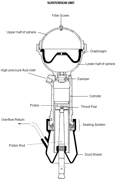
  • Each unit consists of a sphere and a cylinder.
  • The gas is in the sphere which is similar in layout to the main accumulator.
  • The liquid is in the cylinder piston assembly screwed on to the sphere. It is the means by which piston movement is transmitted to the flexible diaphragm of the sphere.
  • The cylinder is mounted on the chassis. It is not rigidly fixed. At the front it is located by two screws and at the rear by a plate.
  • The piston is connected to the wheel arm by a rod.
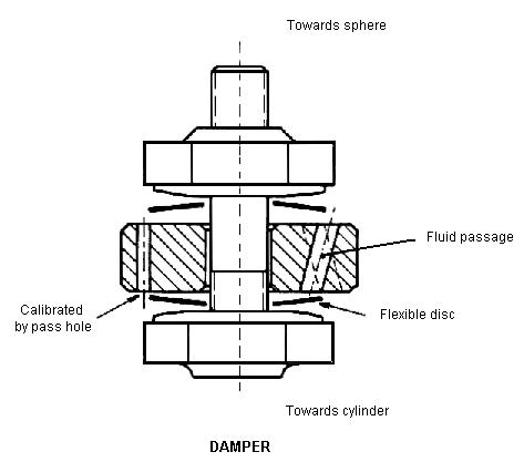
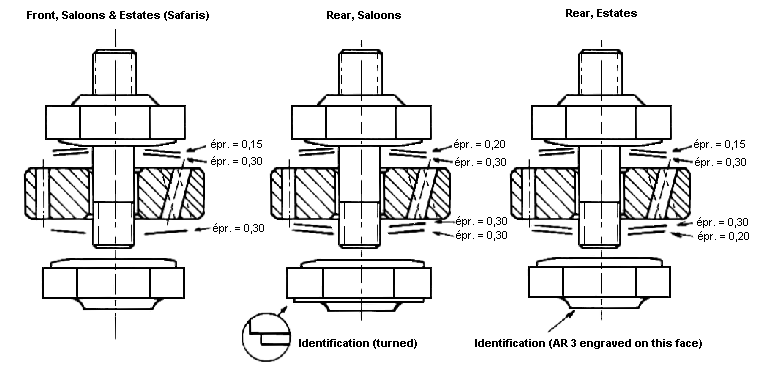
  • A damper is incorporated in each sphere. It is screwed to the sphere, and separates the sphere from the cylinder.


III - OPERATION

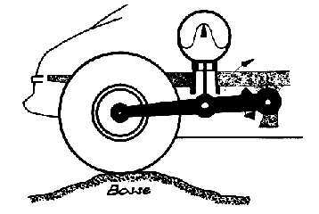
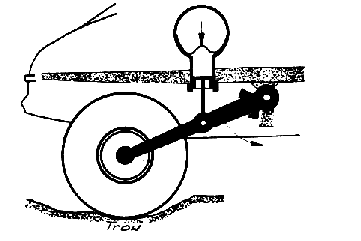
          If it is a pothole, the gas expands and the fluid in the sphere enters the cylinder.

This type of suspension presents definite advantages :

Dampers :

The dampers are double-acting.


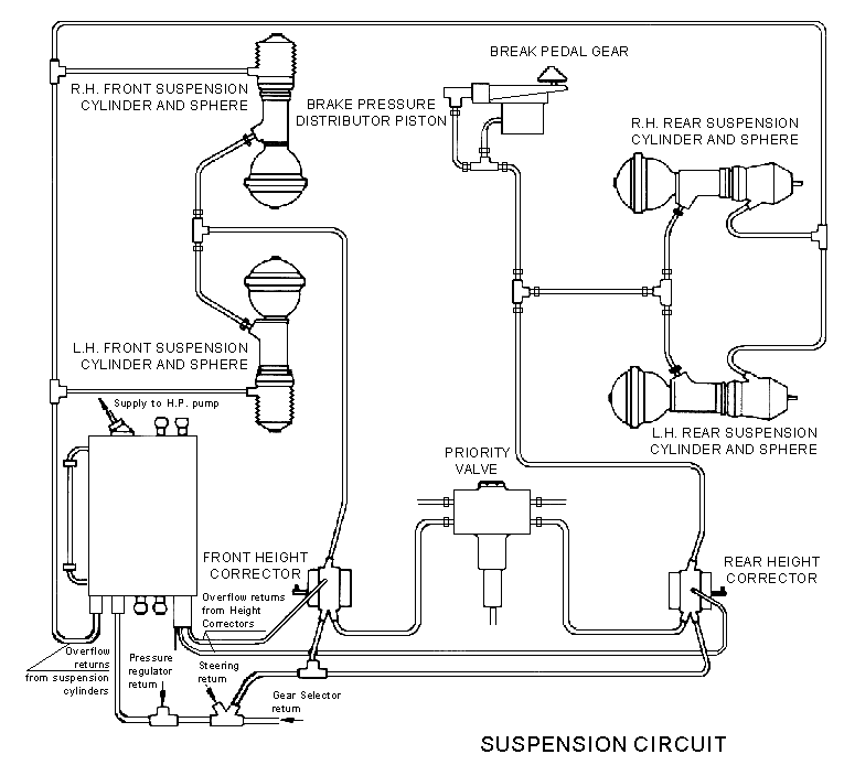
IV - CIRCUIT LAYOUT

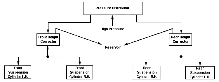
1) All D Models except ID19 B (DV) and ID20 (DT) 
up to December, 1967.

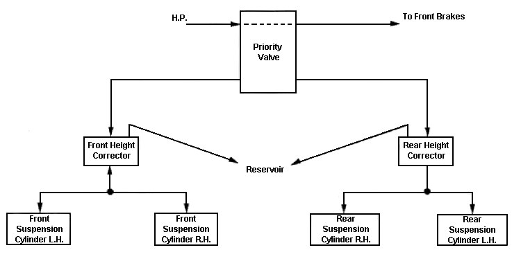
2) All D Models except ID19 B (DV) and ID20 (DT) 
Since December, 1967.

3) ID19 B (DV) and ID20 (DT)

The circuit for these models is identical to layout (2) except that the Priority Valve by a Security Valve.


V - HEIGHT CORRECTOR

  • Height correction allows automatic adjustment of and maintenance of a constant ground clearance whatever the static load.
  • This is obtained by the use of two identical correctors (one per axle) fed by fluid under pressure.
  • Each corrector is controlled by a mechanical linkage which is the automatic height control.
  • In addition, a manual control can be made to act simultaneously on the two automatic controls.
1) The Height Corrector :
a)

Description

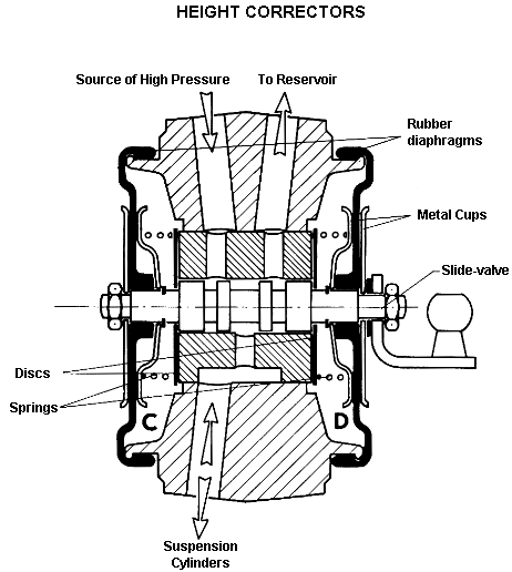
It is a distributor block (3-way tap) which, depending on the position of the slide valve :

  • connects the services (suspension cylinders) to the inlet (HP Supply)
  • connects the services (suspension cylinders) to the outlet (Reservoir)
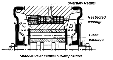
  • isolates both the inlet and outlet from the services (slide valve central).

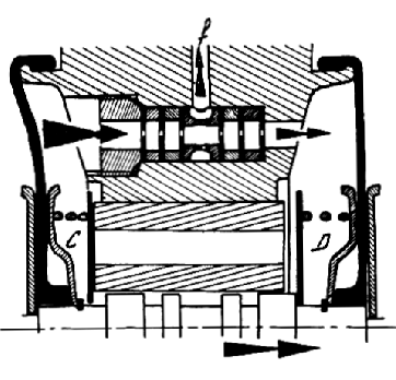
The chambers C and D, sealed by rubber diaphragms (re-inforced by metal cups) are full of hydraulic fluid which comes from the seepage past the slide valve.

A seepage return takes the surplus fluid back to the reservoir.

Chambers C and D are interconnected by :-

  • A clear passage drilled in the sleeve of the slide valve, closed at each end by disc valves controlled by the movement of the slide valve.
    In the central position each disc is held against a face on the sleeve by a weak spring.
  • A restricted passage inserted in the body of the corrector, (a Dash-Pot) which limits the flow of fluid from C to D and back. This passage is connected to the seepage return to the Reservoir.

b) Operation of the Height Corrector.
  • Movement of the slide-valve from the " cut-off position to the "exhaust" position.
    When the slide-valve is moved, that is when it alters its position from "cut-off", the disc valve in chamber C is held on its seating by its return spring, thus closing the clear passage. The disc-valve in chamber D is lifted off its seating by the shoulder on the slide-valve, thus opening the free passage.
    The fluid in chamber C is therefore obliged to pass through the Dash-Pot which slows down the fluid movement, which in turn slows down the movement of the slide-valve. Thus the slide-valve will not move to the " exhaust" position unless there is a positive effort on it for a certain period of time. No correction occurs for small rapid wheel movements.
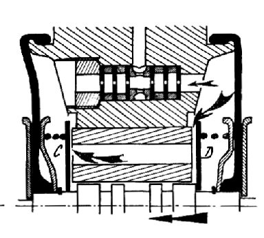
  • Movement of the slide-valve from the "exhaust" position to " cut-off.
    When the slide-valve is returned to the "cut-off" position, the fluid in chamber D can this time use the clear passage and return to chamber C lifting the disc-valve against its return spring.
    So the movement of the disc valve is not restricted, and the return is rapid.
    As soon as the slide valve returns to the "cut-off" position the disc valve in chamber D closes the passage again, stopping the slide-valve over running the "cut-off" position and avoiding a second correction.
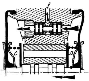
  • Movement of the slide-valve from the " cut-off position to the " inlet" position.
    When the slide-valve is moved the disc valve in chamber D is held against its seating by its spring, closing the clear passage. While that in chamber C is lifted off its seating by the shoulder on the slide-valve, thus opening the clear passage.
    Liquid in chamber D has therefore to pass through the Dash-Pot which restricts the flow and slows down the movement of the slide-valve. The slide-valve will only move to the " inlet" position if there is a positive effort on it for a certain period of time.
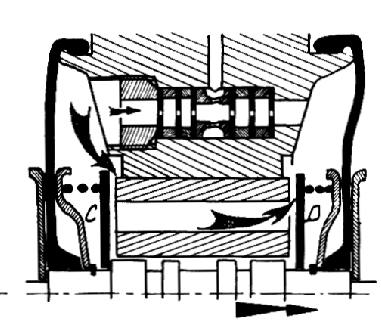
  • Movement of the slide-valve from the " inlet" position to cut-off .
    When the slide-valve is returned to the "cut-off" position, the fluid in chamber C can this time use the clear passage and return to chamber D lifting the disc-valve off its seating against its spring. 
    Thus the valve-movement is not restricted, and the return is rapid. 
    As soon as the slide-valve reaches its "cut-off" position the disc-valve in chamber C re-seats. This stops the slide-valve over-running its "cut-off" position and avoids a second correction.

OPERATION OF THE HEIGHT CORRECTOR (Diagrams)
 

Slide-valve moves from
"cut-off" to "exhaust"

Slide-valve moves from
"exhaust" to "cut-off"

Slide-valve moves from
"cut-off" to "inlet"

Slide-valve moves from
"inlet" to "cut-off"


2) Automatic Height Control :

Let us examine the front control :

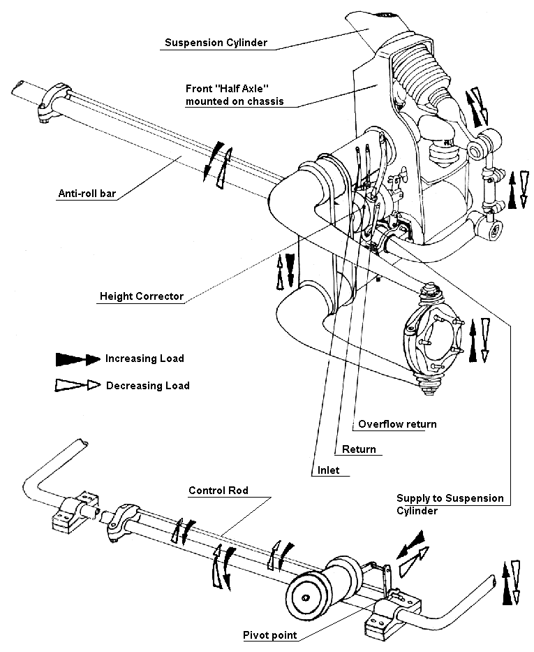
The ball end on the Height Corrector slide-valve is acted upon by a " U "-shaped lever brazed on to a torsion control rod. The control rod is clamped to the centre of the anti-roll bar.

The anti-roll bar is located by two bushes, the pre-loading of which is adjustable by means of spacers. Also two clamps are provided to adjust its end-float.

At the rear the control system is similar, only the anti-roll bar is different.

Operation of the Controls :

As the anti-roll bar is connected to the suspension arms of both wheels, any movement of the latter will cause the anti-roll bar to rotate.

When the chassis is at its normal running height, the angular position of the Height Corrector control rod is adjusted so that it has no effect at all on the slide-valve of the Height Corrector, thus it remains in its "cut-off" position.

To understand the working of the Height Correction system, let us take the simple example of a change in the static load.

An increase in the load causes a movement of the chassis and thus a rotation of the anti-roll bar. This movement is transmitted to the Height Corrector control rod which is therefore twisted, and puts a continuous load on the Height Corrector Control Rod.

The slide-valve is therefore pushed in to the "inlet " position.

Now the amount of fluid between the diaphragm and the piston is increased and the chassis rises. This movement reverses the movement of the anti-roll bar. The load imposed on the slide-valve by the control rod ceases ant it returns to the "cut-off " position. 'The return to the "cut-off" position is rapid, because the slide-valve does not offer any resistance in this direction. The chassis returns to its normal height again.

If the static load is decreased the operations are similar, but the directions of movement are reversed.

Let us now take an example of a dynamic change of load.

  • The movements only last for a very short period of time, the height correction system does not operate.
    In effect, the time of Height Corrector response makes the Height Corrector control rod absorb the movements of the anti-roll bar by virtue of its torsional flexibility.

3)

Manual Height Control :

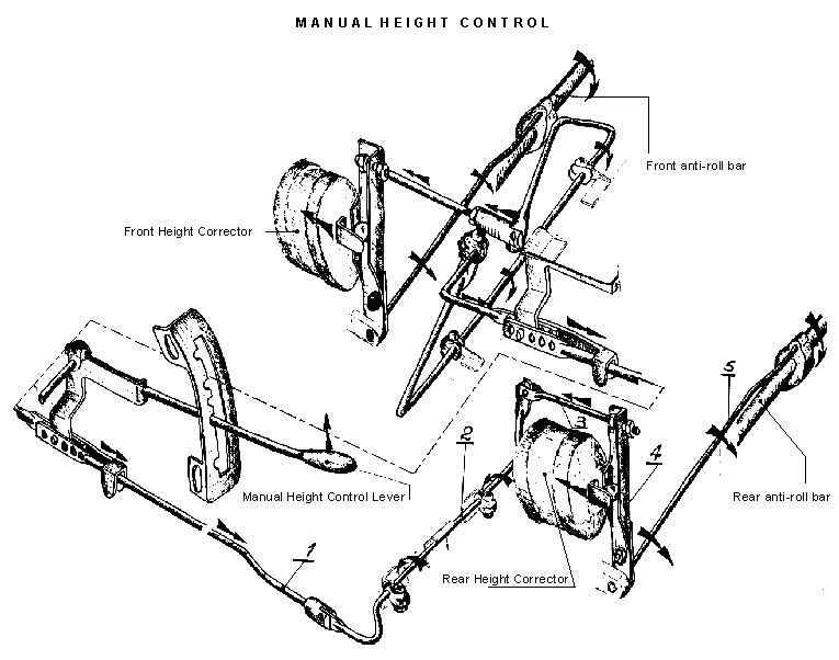
A manual control is provided to override the normal operation of the slide valves and allows the driver to select 5 different positions.

  • "Normal" : This is the normal operating position.
  •  "High " or "Low " : two extreme positions.
  •  Two positions intermediate between "Normal" and "High".

Operation.

The explanation is given showing the rear Height Corrector, but applies equally to the front.

Selection of an intermediate position from " Normal".

The movement of the manual control lever from the " Normal " position to one of the two intermediate positions moves the rear linkage rod (1). 'As this rod moves it acts upon the torsion rod (2) which is located in two brackets fixed to the chassis.

The rod (3), the lever (4) and consequently the slide valve are moved towards the front.

The suspension cylinders are connected to the source of high pressure. The amount of fluid in the rear suspension units is increased.

The car "rises". This "rise " causes the anti-roll bar to rotate, which transmits its movement to the Height Corrector control rod (5) which twists and exerts a continuous pull on the Height Corrector slide-valve, this pull opposes the action of the manual height control.

When the load exerted by the control rod (5) becomes equal to the load exerted by the torsion rod (2), the slide-valve is no longer held in and returns to its "cut-off" position. The suspension cylinders are cut-off from the source of pressure and from the "exhaust" position, the car stabilises.

The pressure existing in the suspension cylinders is the same as when the car is in the "Normal" position, only the volume of fluid has changed.

Selection of " High" or "Low" from "Normal".

The movement of the manual control lever to one or other of these positions exerts a load on the Height Corrector slide-valve by way of the rods and levers, so that the valve is held in the "Inlet" or " Exhaust" positions. The volume of fluid increases or decreases accordingly. The vehicle rises or falls. These movements of the car cause opposite movements of the anti-roll bar which try to cancel the effect of the initial load acting on the Height Corrector slide-valve by the control rod (5). Equilibrium cannot be established because the load created by the control rod (5) is always less than that created by the torsion rod (2). The Height Corrector slide-valve is held in the "Inlet" or "Exhaust" positions. The pressure in the suspension cylinders is either maximum or nil. The chassis rests against the rubber limit stops.

4)

Distribution and Isolation of Pressure  :
a) Pressure Distributor Block ; All D models up to Sept. 1967, except ID 19 B (DV).

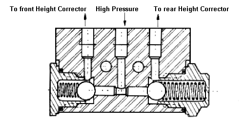
  • The Pressure Distributor Block is a 3-way union which allows pressure to be distributed to the front and rear suspensions. It contains two non-return valves which isolate the suspension from the source of pressure when this is not under pressure.
  • On vehicles with hydraulic gearchange, the pressure distributor block (above) has two non-return valves which have different spring-calibrations. The front valve opens when the pressure reaches 7 bars (100 psi), but the rear valve docs not open until the pressure reaches 35 bars, (500 psi).
  • The initial inflation pressure of the front suspension spheres being 59 bars, (850 psi) and that of the rears 26 bars (370 psi) ; as a result, the fluid from the Source of Pressure first feeds the rear suspension, but only once the pressure has reached 35 bars (500 psi). This pressure of 35 bars (500 psi) is still insufficient to make the front of the vehicle rise, but is enough to ensure de-clutching wich is the aim of the arrangement.
  • On vehicles with mechanical gearchange, the two valves of the pressure distributor block are both similarly calibrated at 7 bars (100 psi).


b) Priority Valve : All D models from Sept. 1967 except ID 19B and ID 20 (DV and DT).

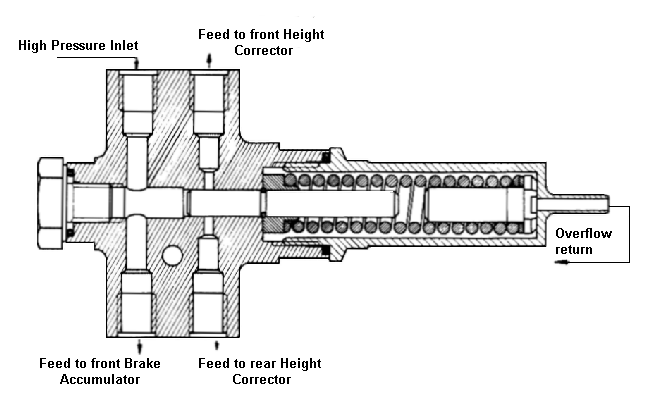
  • The Priority Valve has four ports, two of which (feeds to front rear height correctors) are closed by a slide valve when there is no pressure in the system.
  • When pressure is building up in the system priority is given Co feeding the front brakes.
  • When the pressure is sufficient (110 - 130 bars) to overcome the pressure of the slide-valve return spring, it is moved across and opens the supply to the front and rear Height Correctors.
  • Any seepage between the slide valve and the body of the priority Valve is collected and returned to the reservoir.
  • The valve plays a safety role : its slide-valve isolates the suspension circuits from the source of pressure.

c)

Security Valve : ID19 B (DV) and ID20 (DT)

See chapter 6. (Brakes).


VI - IDENTIFICATION OF PARTS

1) Suspension Spheres :
All the suspension spheres are of exactly the same size. The numbers stamped on the heads of the filler screws enable the spheres to be easily identified. (The numbers correspond to the initial inflation pressure).
  • Front Spheres, all models 59 (bars)
  • Rear Spheres, saloons      26 (bars)
  • Rear Spheres, Estates      37 (bars)
2) Suspension Spheres :
Three types of cylinders :
  • Front Cylinders, all models  ø 35 mm located by screws
  • Rear Cylinders, saloons      ø 35 mm located by a plate
  • Rear Cylinders, Estates       ø 40 mm located by a plate
3) Dampers :
  • Since September 1965, the dampers are modified. They are identifiable by a radius, (instead of a sharp corner) machined on the head of the retaining nuts, on the cylinder end (nut marked).
4) Height Correctors :
  • These are identical front and rear, on all models.
5) Pressure Distributor Blocks : two types :
  • For vehicles with mechanical gearchange : may be fitted either way round.
  • For vehicles with hydraulic gearchange : must be fitted with the larger of the two caps at the end feeding the tear suspension.

Back to top of page