Braking System

| General Details | The DS Braking System | The ID Braking System |


I - GENERAL DETAILS

All 'D' models are fitted with disc brakes at the front and drums at the rear.

There are two different systems on these vehicles.

  • The DS system
  • The ID system

There are many similarities between these two systems.

  • The front and rear circuits are separate.
  • The rear brakes are fed from the rear suspension (this method of connection allows the maximum pressure in the rear circuit to be limited).
  • There is a reserve of pressure for the front brake circuit :-A brake pressure accumulator in the case of the DS system, the main accumulator in the case of the ID system.

II - THE DS BRAKING SYSTEM

 - (All DS models and estates)
1)

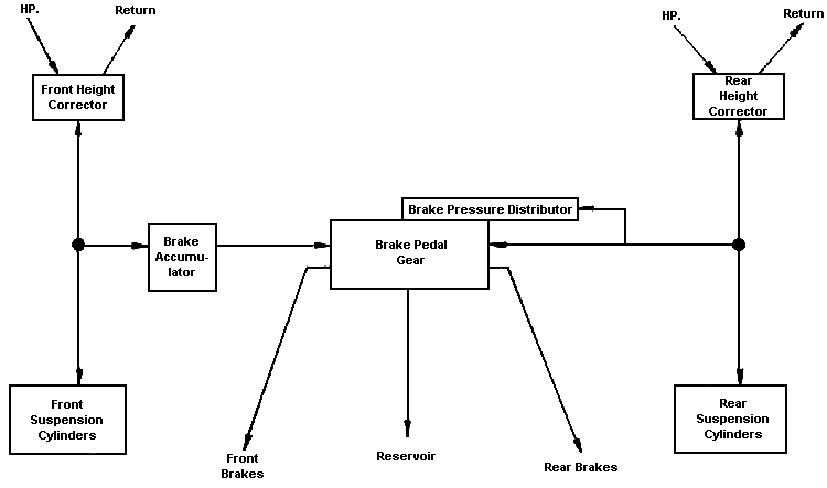
Circuit Layout

a) Until December 1967

  • The front brake circuit is fed by the front suspension, the front brake accumulator is connected into this circuit.
  • The rear brake circuit is fed by the rear suspension.
  • The brake pressure- distributor piston is fed from the rear suspension also.

NOTE : The pressures in the suspension circuits, which vary with the load, are as follows :

  • front : 85 - .110 bars 1200-1565 psi. depending on load
  • rear : 50 - 90 bars 720-1280 psi. depending on load

b) Since December 1967

  • The front brake circuit is fed directly from the source of pressure, the front brake accumulator is connected into this circuit.
  • The rear brake circuit is fed from the rear suspension.
    The brake pressure distributor piston is fed from the rear suspension also.
2) Description :
a)

The brake accumulator

  • The design and operation are identical to those of main accumulators of the machined forged steel pattern. It is fed either by fluid from the front suspension or from the source of pressure.
  • A ball-type non-return valve stops fluid escaping back through the feed line.
  • With the engine stopped, or in the event of a failure of the source of pressure, this accumulator provides a reserve of fluid under pressure to enable the vehicle to be stopped.
  • The initial inflation pressure, stamped on the filler screw, is 40 bars - 570 psi.
b) The brake pedal gear :
This comprises :  - The brake pedal assembly
- The hydraulic control valves
- The pressure warning light switch
- The brake pressure distributor
  • The brake pedal assembly carries the actual pedal plate which is covered by a rubber moulding and provides a measure of progressivity to the driver's effort.
  • The hydraulic valve assembly :
    This assembly comprises two identical pressure-control slide-valves. The slide-valves are connected by a pressure distributor plate.
    The force on the brake pedal is transmitted to the pressure distributor plate by means of 
    adjustable rollers A.
    Details of these pressure-control slide-valves.
    • When at rest, the supply line to the brakes is open to the return to the reservoir. (No residual pressure in the brake circuits).
    • A return spring moves each slide-valve back to the "at rest" position.
  • The pressure warning light switch operates on the pressure in the front brake accumulator, and illuminates a warning light on the dash board when the pressure is between 60 and 80 bars (870 to 1160 psi.).
  • The brake pressure distributor :
    • The cylinder of the brake pressure distributor is fed by fluid from the rear suspension (it is at the rear that the variations of pressure in relation to load are greatest),
    • The pressure in the supply of fluid acts on the surface S1 of the piston.
    • The piston is connected to the rollers A.
    • A spring returns the piston to its rest position.

3)

Operation :
a) The hydraulic control valves :

The driver applies the brake.

The pressure distributor plate receives the effort T. 

The slide valves are moved down, closing the return ports, then opening the inlet ports.

This establishes in the front and rear circuits, pressure ; p & p'.
These pressures act on the undersides of the slide valves (chambers B) providing "feel" at the pedal. This reaction balances the force T :

T = (p + p')S

The sum of the two pressures is thus proportional to the force generated by the driver pressing the pedal and independent of the supply pressures. By controlling the force on the pedal, the driver controls the power of the braking.

b) The Brake Pressure Distributor Piston :

With a pressure of 60 bars, (870 psi), in the Distributor cylinder the force T is applied to the middle of the Pressure Distributor Plate.

The pressures in the front and rear circuits are therefore equal (p — p') but, because of the methods of construction, the braking effort is greater at the front than at the rear ;

  • At the front, the diameter of the two pistons in each caliper is 60 mm
  • At the rear, the diameters of the pistons in the wheel cylinders are : 18 mm on all Saloons 20 mm on Estates

If the pressure in the rear suspension increases, the piston in the Pressure Distributor moves the rollers.

The pressure point of the rollers and thus of the force T moves towards the rear valve.
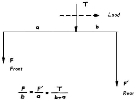
The force F' being greater than F, the pressure in the rear brake circuit rises (p' greater than p) and the preponderance of braking effort at the front diminishes.


III - THE ID BRAKING SYSTEM

1)

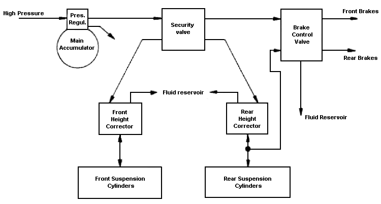
Circuit Layout

  • The front brake circuit is fed from the source of pressure.
  • The rear brake circuit is fed by the rear suspension.
2) Description :
a) Security Valve :
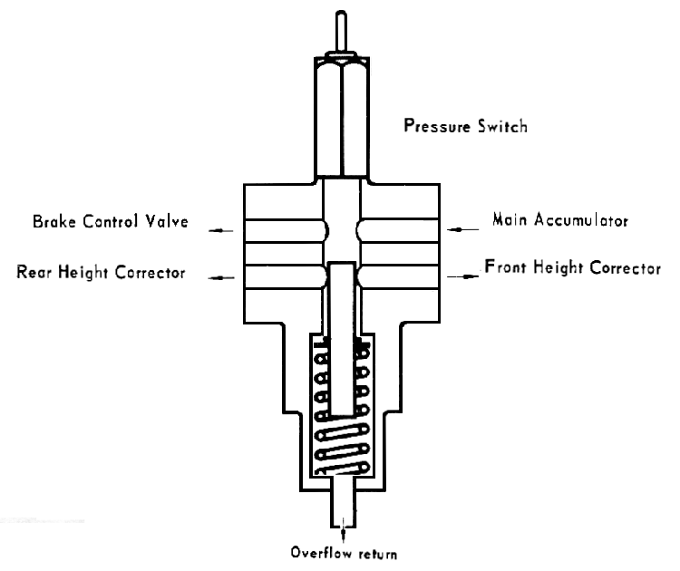
  • This comprises basically a 4-way union of which two ways (front and rear suspensions) are blanked off by a slide-valve when there is no pressure.
    A seepage return pipe takes any seepage from between the slide-valve and the valve body back to the reservoir.
  • On this valve is fitted the pressure warning light switch.
b) The brake control valve.

This comprises two pressure-control valves. These slide-valves are co-axial. They are grooved circumferentially in order to relieve any side-thrust from the source of pressure.

A single dash-pot in the lower end of the control unit operates for both slide-valves.
The slide-valves are returned to and held in their "at rest" positions by return springs.
It should be noted that when the valves are "at rest" the supply lines to the brakes are open to the common exhaust port. (No residual pressure in the circuits).

3)

Operation :
a) Security Valve : When the pressure rises in the circuits, priority is given to feeding the front brakes.
When the pressure is sufficient (70 - 90 bars 995 to 1280 psi) to overcome the return spring on the slide-valve it opens the ports to the height correctors.
The slide-valve is a safety device, it isolates the suspension circuits from the source of pressure
.
b) ID type hydraulic brake control :
  • When the driver applies the brakes :
    The pressure-control slide-valve for the front brakes moves down, closing the exhaust port and opening the inlet.
    A pressure p is established in the front brake circuit. The same pressure is established in the chamber C1 beneath the slide-valve.
    The pressure-control slide-valve for the rear brake circuit does not move until the pressure p is sufficient to compress the spring R2.
    When this pressure is reached the slide-valve moves down, closing the exhaust port and opening the inlet port.
    A pressure p' is established in the rear braking circuit and in the chamber C2 beneath the lower slide-valve.
    This pressure p1 generates a force on the underside of the lower slide-valve which balances that on its upper face in the chamber Cl. The rear brake slide-valve stabilises and the pressure p' is regulated and stabilises.
    As p' stabilises, the pressure p in the front brake circuit adjusts after its slide-valve stabilises.
    The pressures in the front and rear brake circuits are proportional to the pressure on the pedal and independant of the supply pressure. By controlling the pressure he exerts upon the brake pedal, the driver controls the pressure in the brakes.
  • When the driver releases the brakes :
    The pressure-control slide-valve for the front brakes, under the influence of its return spring Rl, and the pressure p in chamber Cl takes up its normal "at rest" position. The pressure p drops.
    The slide-valve for the rear brakes, under the influence of its return spring R2 and the pressure p' in the chamber C2, returns to its normal "at rest" position. The pressure drops.

c)

Preponderance of front braking : Pressure rises in the front brake circuit first.
When this pressure is sufficient to compress the spring R2 the rear brakes are fed. This distribution of braking pressure is independant of the load in the car. The difference is maintained no matter what the pressure is on the pedal.
d) Reserve of pressure : The main accumulator is also the brake accumulator. Because of this its initial inflation pressure is lower (40 bars (580 psi,) instead of 65 bars (949 psi) than a normal main accumulator. This allows a larger reserve of fluid under pressure for the brakes.
The pressure warning light operates on the pressure in the main accumulator.
It lights the warning lamp on the dash when the pressure is between 85 and 55 bars (1210-780 psi).

4)

Operating Units :
  • At the front the brake pistons are 60 mm in diameter.
  • At the rear the brake pistons in the wheel cylinders are 18 mm in diameter.

SECURITY VALVE

BRAKE CONTROL VALVE

Back to top of page