|
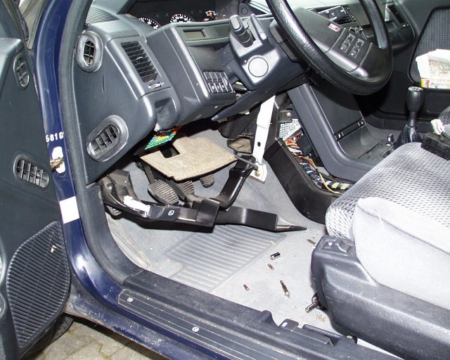
Fig. 1 : Panel under the steering wheel and carpet covered
panel removed.
|
|
When the panels have been removed the flap motor servo
unit is visible under the dash. Unfortuneatly the front screw that mounts
the servo to the heater box can not be accessed because the of large white
connector (See Fig. 2 and 3). The rear screw is not visible at all, here a
very short screwdriver is needed because of the limited space.
|
|
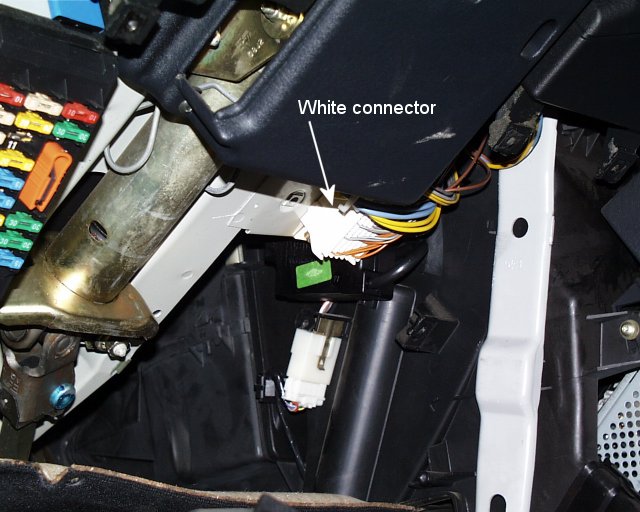
Fig. 2 : The heater flap servo is now visible, it's small
black plastic box with the green sticker.
|
|
The white connector has to be removed in order to be able
to access the front screw. The connector is bolted to the frame with two
bolts, removing is easy.
|
|
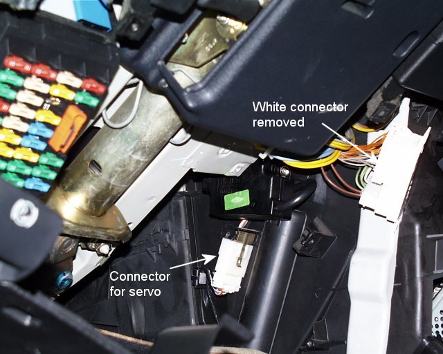
Fig. 3 : After removing the white eletrical connector unit
the rear mounting screw is accessable.
|
|
After the heater flap servo has been removed (Fig. 4) one
can see the two mounitng points and the heater flap axis with the small
lever-arm (which is probably there for the cars with manual heater control).
|
|
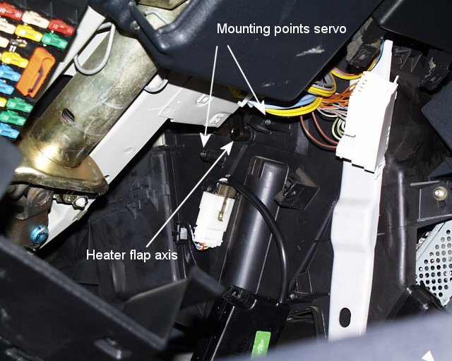
Fig. 4 : The servo is now removed, it's hanging from its
electric cable.
|
|
The servo axis is flattened at one side (see Fig. 5), the
hole in the heater flap axis has the same shape. Both axis will fit together
at one position only, so make sure that the servo axis is in the same
position after reassembling.
|
|
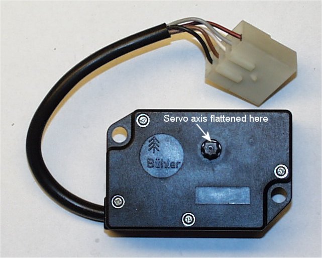
Fig. 5 : The complete heater flap servo.
|
|
The servo is easily opened by unscrewing the four screws (see Fig. 6). Take
care while pulling apart the two halfs of the servo box in order not to tear
the rather fragile seal (see Fig. 7). Please note the arrows on the big gear
wheel (that drives the flap) and the smaller gear wheel (that drives the
servo potentiometer) at the right. On both gear wheels there is an arrow,
they have to be aligned when the servo is reassembled.
|
|
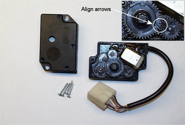
Fig. 6 : The heater flap servo box opened.
|
|
The two gear wheels mentioned above are easily removed
(just pull them upwards).
|
|
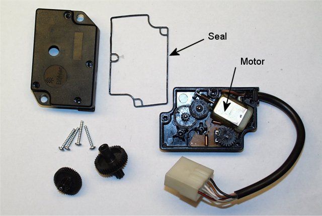
Fig. 7 : The heater flap servo partly dissasembled.
|
|
Now the little motor can be removed together which
the circuit board (PCB). The motor is is soldered onto the PCB.
|
|
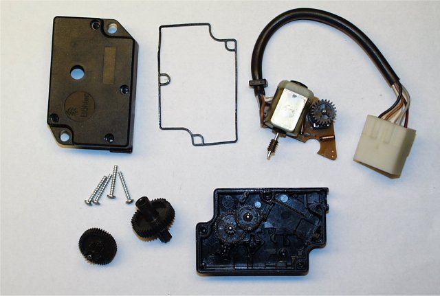
Fig. 8 : The heater flap servo almost completely
dissasembled.
|